
THE BORING PART ABOUT HOW I GOT TO HACK THE MICROPHONE
I have a set of Sony ecm-aw3 microphones. They are good for the money they are worth but they have some weaknesses that can be addressed with a little ingenuity.
These are simple bluetooth microphones that won’t break the bank. You turn them on, they pair without having to input any codes (not that you can do it anyway) and away you go.
They claim to have a range of up to 50mts. I have managed to use them up to 30mts away with clear line of sight with no interferences.
Amongst the pros of using them are the fact that they run on one AAA battery for the transmitter and one for the receiver, they have walkie talkie capabilities so the camera or sound operator can communicate with the person talking by using the in ear monitor (included 2 sets one for the transmitter end and one for the receiver end), the sound quality is quite good and clean considering they work on the bluetooth spectrum, and they are small and light to carry around.
The cons are that bluetooh is crowded and works on the 2.4ghz spectrum which is shared by Wifi, microwaves and a plethora of other devices. But if you find a nice relatively clean area it won’t be a problem. Some people claim that they are power hungry, but I have managed to get over 3 hours of use from a single pair of batteries, Just carry spares and or rechargeables.
My main gripe with these microphones is the fact that you can’t just plug a different microphone to the transmitter and mix and match depending on your needs. They have an internal microphone inside the transmitter casing (actually they have one inside the receiver casing as well so I thing you can use either one as transmitter and either one as receiver). They do have a clip and a wind sock of sorts but if you are interviewing someone you are left with the difficult job to try to hide the rather unsightly transmitter or putting it off camera. The microphone is quite sensitive and picks up the sound even if you wear the transmitter on your belt, but it also picks up every single sound produced by movement, clothes rubbing, a big deal of wind, etc.which makes the microphone virtually a pain to use them anywhere but in the quietest of the rooms.
WHEN THERE IS A WILL THERE IS A WAY.
THANKS TO MATT aka. BANDITT.
I started to think about ways to overcome that limitation and after much thinking and research I found an old post about someone hacking an old Sony ECM-HW1 which was a similar microphone produced by Sony to be used with some of their videocameras with an active shoe connection. The main difference being that the transmitter in that unit was bigger (2xAAA batteries instead of 1) and that the microphone could be disconnected by a little connector inside the casing.
Said post was so old that even the photo links were broken and I was trying to make sense of the instructions.
That post by Banditt was what made me decide to take the plunge. After all the microphone was already out of warranty and I had a lot to win.
THE PROCEDURE. INSTALLING A 3.5MM SOCKET TO ALLOW YOU TO USE DIFFERENT MICROPHONES WITH YOUR ECM-AW3.
Disclaimer: If you are thinking about hacking your microphone I won’t be held responsible for any damage that you may cause to the unit, nor I ‘ll be held responsible for voiding the warranty or any personal injuries, money loses or otherwise that you may sustain while attempting this hack. It is entirely up to you if you wish to proceed and I wish you good luck.
First you will need to source the parts that you are going to need which basically are:
A soldering station. I suggest you to invest money and buy a soldering station with temperature control. They work much better than the soldering irons, so you won’t overheat the components or run the risk of toasting the PCB or anything else. Read a couple of webpages about soldering electronics to understand better how it works.
PCB holder, soldering assisting clamps with a magnifying glass. Because you will need more than two hands.
Drill and and 2mm drill bit. To create the holes to feed the new wires.
Hot glue gun. If you have a better way to attach the socket to the chassis of the microphone please share.
1 x 3.5mm Stereo SWITCHED PCB Socket with 5 tabs. You can get it from Jaycar in Australia, they are cheap and what I like about it is that, as suggested by Banditt, you can use one of these and that way the internal microphone will only deactivate when an external one is plugged in. So the modification allows you to use the microphone in the way intended by Sony or in a more versatile way. Why stereo if the microphone only has mono-aural capabilities? I let Banditt explain that one better:
Now your thinking stereo socket….why? The receiver is only mono, but if you end up using a stereo mic you can just jumper the lead over and that way pretty much any non-powered mic will work. It will just end up feeding both signal channels into the 1 side. The circuitboard will not know the difference(…) BIG NOTE: IF YOU USE A MONO MIC JACK (The kind with only 1 band around it) YOU WILL GROUND OUT THE MIC AND IT WILL NOT WORK. LEAVE THE JUMPER WIRE OFF IF YOU INTEND TO DO THIS. OTHERWISE THE STEREO JACK WILL BE FINE.
I used the stereo socket but did not put the jumper in as I didn’t think I would use stereo mics with this unit. But I will give you the diagram with the option.
Links to the socket for Jaycar in Australia and RadioShack in the USA:
JAYCAr 3.5mm stereo switched PCB socket PS0133
RADIOSHACK part number 274-246
CABLES. You are going to need thin cables. I just used an old USB cable that I had which had damaged plugs. They are about the same gauge that the ones used inside the microphone. Could not get a black one but used the brown one and the red.
THE SURGERY BEGINS

The first thing you need to do is to open the casing of the microphone. I tried to pry it open gently but that was not going to work and was going to leave marks all over the case. I put a few little dents, but then decided to do it differently.
The top cover of the microphone (Where it says bluetooth and microphone) is just that, a cover. It attaches to the bottom section with some tabs. The best way to open it is by putting your finger inside the battery compartment and start to pull outwards to the sides. It will make the side flex enough so the tabs dislodge from the inside. Be careful not to use excessive force. once the side and the top are free the other side comes easily.
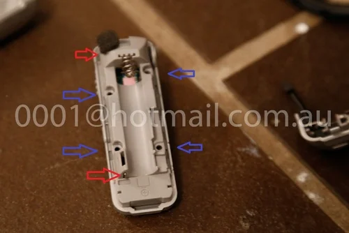
The tab locations are indicated with red arrows.

Once the top cover is removed there are four phillips head screws that are holding the battery tray attached to the lower part of the casing. I did not take a photo of the screws but you will see them once the cover is off (Blue arrows).
Be careful when removing the tray because the actual microphone piece is under the foam rubber at the top. Guide the cables out through the slot on the side (top red arrow).
The lower contact for the battery is similar to a clothes peg spring (the positive side) you can see it just popping its end at the bottom (lower red arrow).
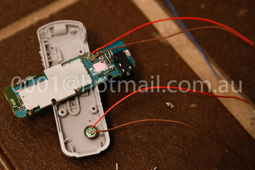
If you have got this far now you will have the PCB exposed and can see how the microphone piece is soldered to the PCB.

After that I decided that the length of the wires was not going to be enough so I replaced the wires with some out of my old USB cable. be generous and leave enough cable for later. Better to cut a bit than to have it too short and not enough for the rest of the procedure..

First remove the microphone from the PCB, use a heat gun or your soldering station, be gentle and quick. Then solder new wires remembering the polarity. Do the same with the microphone piece.
At this stage you will need to drill two holes to feed your wires. The first hole I drilled was in the battery tray. To the side of the negative battery terminal.
Then put the top cover over the battery tray and mark the position for the external hole. Try to keep it to the side so the wires don’t impede the battery access. This units have little room to spare.
Before feeding the wires remember to mark the wires so you know which ones go where. Put the microphone in its rightful place and feed the cables through the slot and then back up through the hole you just drilled.
Because they were the same colours I decided to twist together the ones from the PCB and leave the ones from the mic loose.

Now, put back the four screws that keep the battery tray in place. Be careful when putting the battery terminals, remember to put the positive one through the slot at the bottom and then push back upwards before settling the tray. Verify that the negative terminal coil is fed into the grooves

Feed the wires through the hole you drilled in the cover. Don’t close the cover just yet in case you need to go back inside to fix anything.

Now we need to solder the wires to the socket.

The two black wires (brown in my case) are going to the common ground tab (red 1).
The positive (red) wire that comes from the PCB goes to tab number 2 (green 2).
The positive (red) wire that comes from the microphone goes to tab number 3 (blue 3).
Tab 4 is unused.
Tab 5 is a tricky one:
Remember the quotation to Banditt before? Well. You have to decide if you have enough external microphones that have an stereo plug. If you have plenty of those microphones then just bridge tab number 5 to tab number 2 and you can trick the PCB to admit both channels into one. If you plan to use it with mono-aural microphones then leave this tab free or you will ground the mono mic and it won’t work.
I did not bridge it in mine.

It is probably wise to test the microphone now before you close everything. Put a battery in and check it goes in without issues. Then test for functioning of the internal microphone and then connect an external and test too. The internal should deactivate when an external is plugged and it should come back on once you unplug the external mic.
Now decide the location and orientation where you want to have the socket attached to the casing. Make sure it doesn’t get in the way of any other button.


Once you are happy with it. Tidy up the wires and stick the plug to the chassis with the hot glue gun. Be generous and maybe put some over the wires and the hole you drilled in the chassis.
Try to be tidy, but it is difficult to mould the hot glue to make it look nice.


And that is it. You have a truly versatile bluetooth microphone. I will link to some raw sound samples so you can compare it.
As Banditt said years ago about his hack:
Banditt said:
"Ok may not be the best hack but damnit I’m proud of it!!"
So am I mate! So am I!
WAV raw file straight from the Zoom H4N comparing the hacked mic with an external lapel, the internal microphone and the onboard stereo microphone from the h4n Zoom:
https://www.dropbox.com/s/3wtqp4gfwwpfzr6/130921-005.wav
PS: Canon is selling one microphone that is exactly the same with a slightly different casing. I think that one makes another good candidate for this hack.